
ATS Wiring Diagram Tutorial
The Bernini Design ATS controllers are designed for a wide range of standby applicatioins applications. You can get the most from ou technology when you connect an old or second-hand generator. Thanks to the wide range of programmable inputs and outputs, you can connect all kinds of electric-start engines 12 V or 24 V.
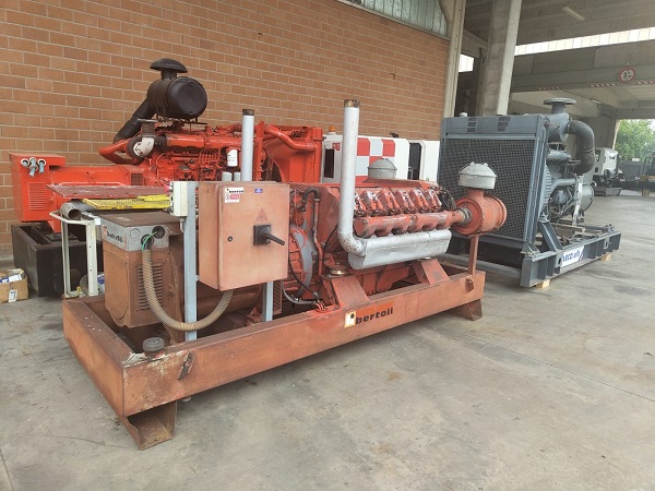
Engine & Miscellaneous Connections
The controller inside an ATS or AMF panel interfaces with all kinds of switches and offers 3 fully configurable digital inputs. Digital inputs are meant to be connected to a battery minus (the GND, if you will) with "polarity-free" contacts. Applying voltage to digital inputs may cause erratic functionality. For each input, you can choose one of over 20 options depending on the controller. By default, input 3 is always configured to "REMOTE ENGINE TEST INPUT".
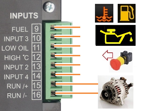
In the same way, input 2 is configured as "REMOTE LOCK INPUT", while input 4 is configured as "MAINS SIMULATED INPUT". All inputs are protected against overvoltages, AC voltage up to 50V, and reverse polarity.
The Analogue Inputs
The analogue inputs are only available with AMF controllers like Be142 and BeK3. To get accurate measurements, the controller offers a "ground compensation" terminal. It senses and cancel eoor measuremts due to ageing of the connections.
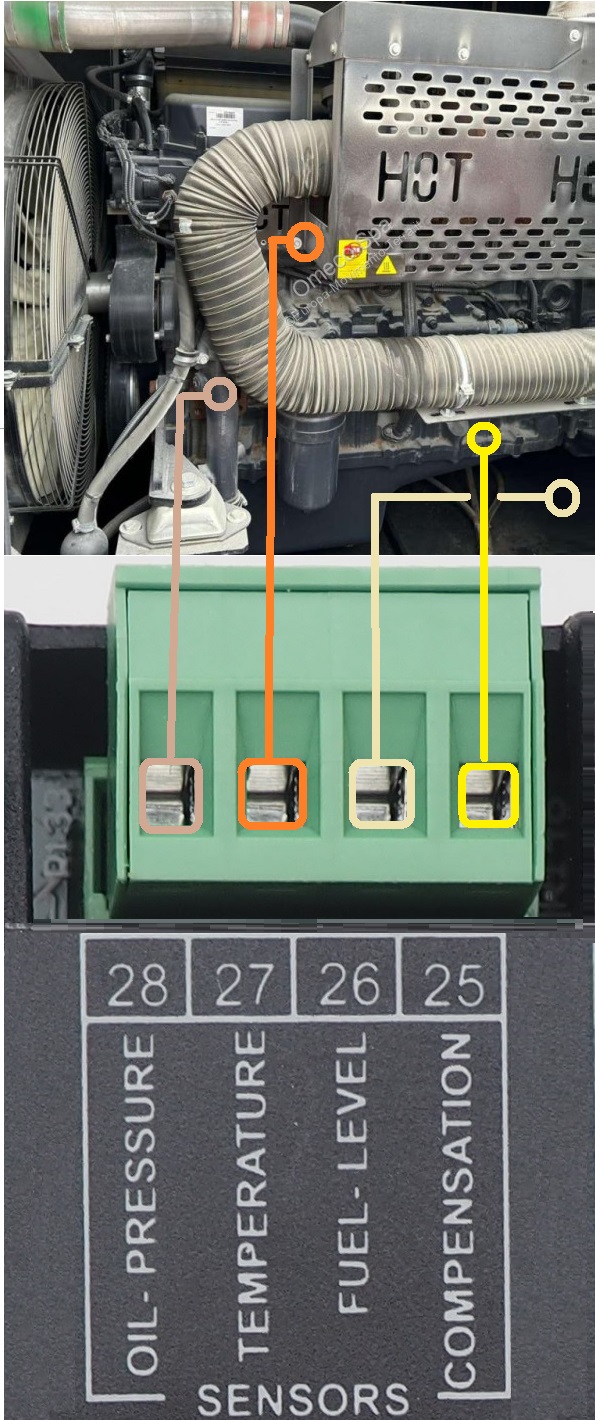
Typical analog input for an engine are: Oil Pressure, High Temperature and Fuel Level.
Connecting the Digital Outputs
The controller DC outputs feature short-circuit-proof relays. The outputs are designed for driving automotive relays. The total current delivered by the outputs must not exceed 4A. Over this current, the controller triggers the output short-circuit protection to shut down it.
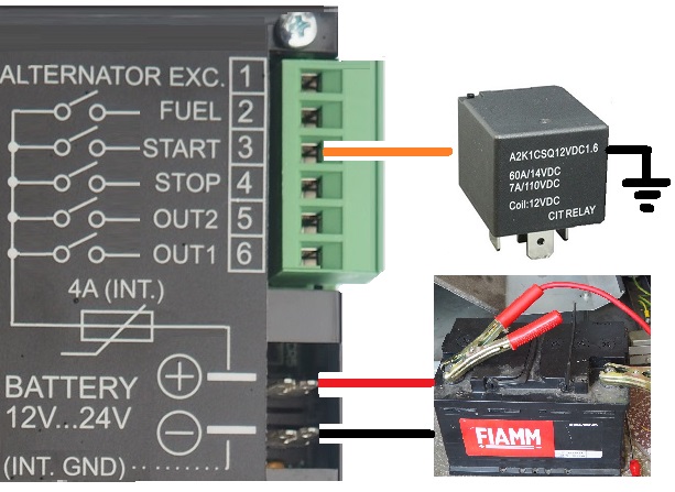
OUTPUT 1 is programmed by default as "ALARM OUTPUT". You can connect a sound alarm. The OUTPUT 2 is programmed by default as "PREGLOW". You may install a pilot relay to start a diesel engine. Custom made AMF and ATS panel may feature additional extension boards. You can get up to 16, contact-free, relay outputs.
Connecting 400V
The ATS controller directly interfaces with GENERATORS and UTILITY POWER LINES up to 600Vac. The fuses indicated in the picture are mandatory. These fuses (or a circuit breaker as an option) protect the wires in case of a direct short-circuit.
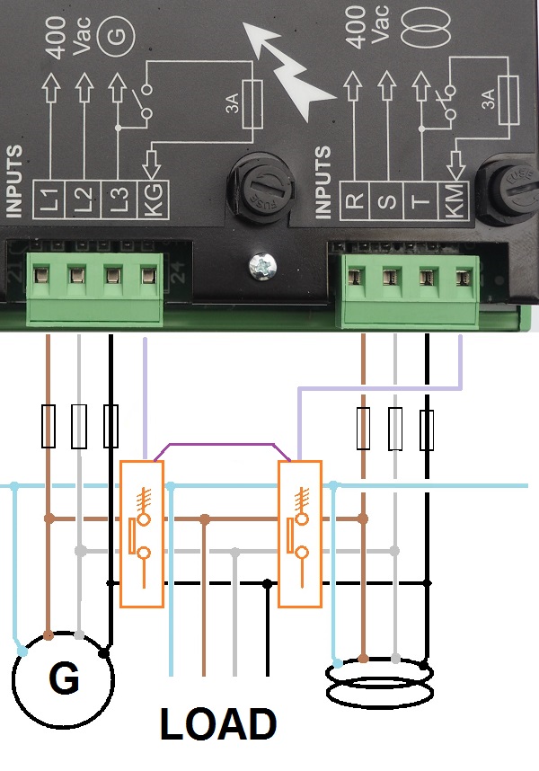
You will find more details about the internal ATS or AMF panel wiring including contactors explanantioin in the following PDF document:
The "Big Picture" of a general-purpose ATS panel is as follow:

The ATS panels manage high currents. The best option is to connect the wires directly to the transfer switch body using 12 M8 or M10 bolts. A good practise is to limit the current for the generator and mains to no more than 20% of the panel's nominal rating via external circuit breakers.
The "Big Picture" of a general-purpose AMF panel is as follow:
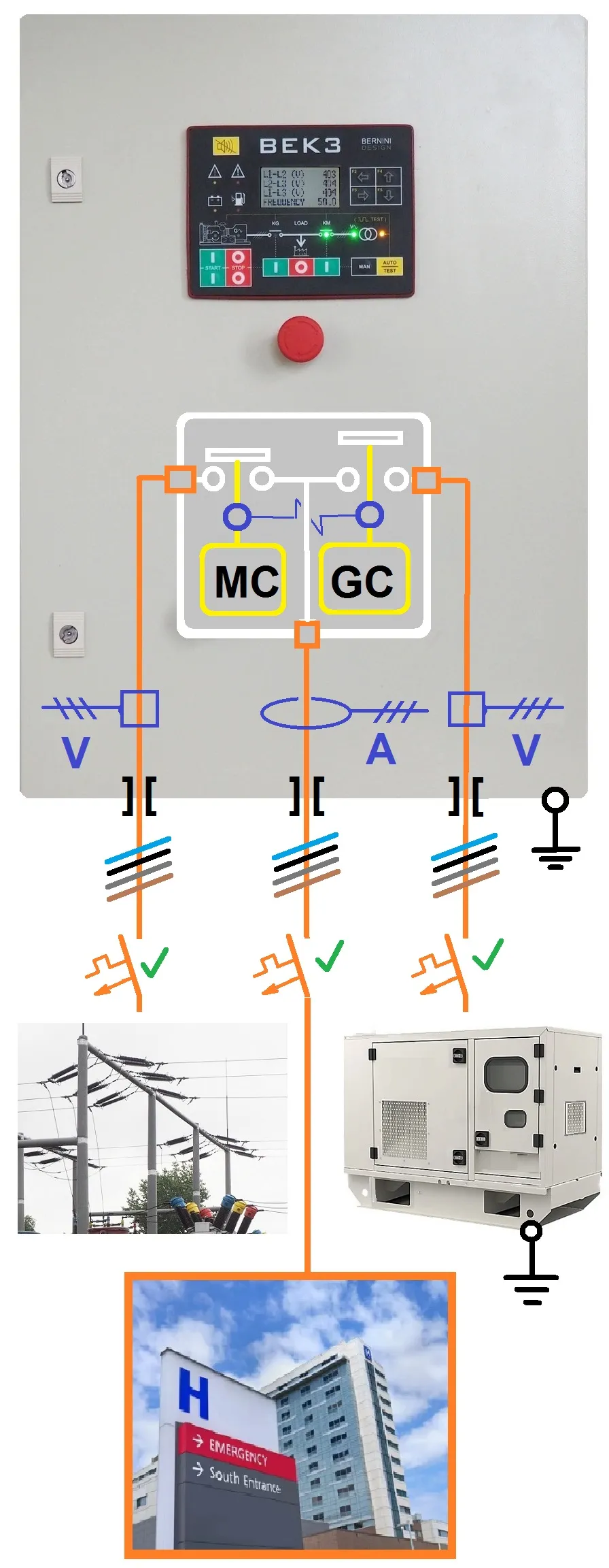
If it is about high-current rated AMH panel the best option is to connect the wires directly to the contactors body using 12 M8 or M10 bolts. Standard AMF panels up to 60 kVA features professional, industrial-grade, terminal blocks. A good practise is to limit the current for the generator and mains to no more than 20% of the panel's nominal rating via external circuit breakers.
Current Transformers
All AMF and ATS panels feature current transformers of a suitable size. To get precise measurements of the current that flows in your LOAD you must ensure a perfect grounding for the panel and generator. Voltage differences between neutral and ground may introduce significant errors.
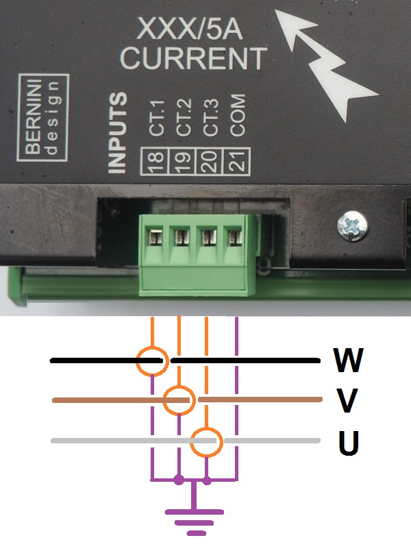
The ATS or AMF controller is factory programmed according to the CT size. But, we recommend that you carefully set up the limit for overlaod (overcurrent) warning and shutdown.
ATS Panel Wiring Diagram PDF
If you are looking for ATS panel wiring diagrams, our comprehensive PDF tutorial provides the optimal solution for your standby generator. This guide includes practical study cases to clear up any doubts. With suitable controller proposals, we cover all your needs—from 5kW (single-phase 230V) up to 200 kVA (3-phase 400V).
Buy the ATS Panel Wiring Diagram PDF 4,90€
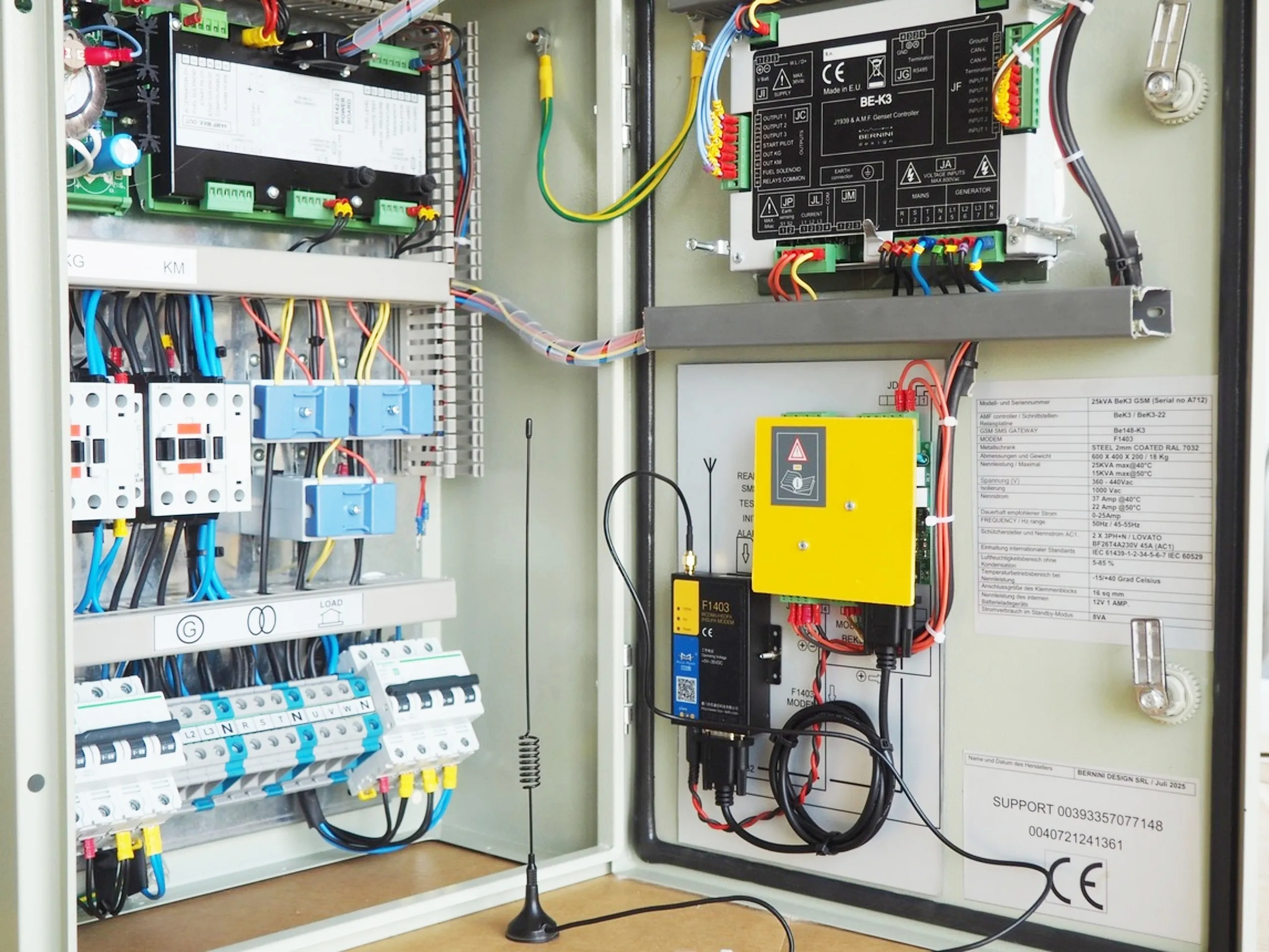
There are two options for connecting the LOAD to MAINS or GENERATOR: via contactors or a motorized changeover.
These are based on the technology used to transfer the LOAD from MAINS to GENERATOR and vice versa. Let us see an overview before diving into the schematics wiring diagram. The ATS controller governs the system and transfers the load to the GENERATOR or MAINS smoothly and with short downtime. A delay time between the switching it is mandatory. Advanced ATS controllers like BeK3 and Be242 feature an adjustable delay time. It will avoid dangerous sparks on the contactors or transfer switches. The ATS controller adds a delay before activating a LOAD. A fast switching form GENERATOR to LOAD, for example, could be dangerous in case of inductive loads. In general, the ATS connect the LOAD only if the primary (call it MAINS) and secondary sources (call it GENERATOR) are stable within appropriate settings.
Buy the ATS Panel Wiring Diagram PDF 4,90€
Bernini Design Srl