
Typical Specifications
In this page, we publish the typical specifications for a contactor changeover and motorised changeover ATS panels. The specifications cover all electrical, electronic and mechanical aspects. For simplicity we publish two relevant examples: a 125A/ 80 kVA with a motorised-switch changeover and 25 kVA contactors-based changeover ATS panel.
Email bernini@bernini-design.com to ask for any particular size.
40A / 25 kVA ATS Panel Specifications
This ATS panel features a contactors-based changeover technical solution.
| Description | Notes |
| Product origin /Manufacturer | EU/Bernini Design Srl |
| Model-ATS | 25 kVA / Be242 |
| Structure / Protection | Metal cabinet / 1,5mm / IP62 |
| External Dimensions | 50 X 40 X 20 / 20 kg |
| Rated Nominal Power @ Ambient °C | 25 kVA @ 35°C |
| Continuous Power @ Ambient °C | 20 kVA @ 35°C |
| Rated Voltage (3-Ph+N) | 400 Vac / 360-440 Vac |
| Insulation Voltage | 1000 Vac |
| Rated Current AC1 @ 400Vac | 40 Amp |
| Continuous Current / Short Circuit | 0-30 Amp @ 400 V /50 kA |
| Frequency Range | 45 Hz - 55 Hz |
| Electrical Protections | Min-Max V-Hz, Max Amp |
| Changeover | 2 x Lovato BF26T4A |
| Norms or Standards | IEC 61439-1-2-34-5-6-7 IEC 60529 |
| Internal Protections | Various Fuses |
| Humidity Class | 5-85 % No condensation |
| Operating Temperatures | -5/+35 °C Nominal (50°C max.) |
| Temperature-Dependent Power Reduction | Reduce power 5% for each degree °C above 35 °C |
| Connections | Terminal Blocks 25 mmq |
| Battery Charger | 12 V / 1 A |
| Standby Power Supply | 8 VA |
40 A / 25 kVA ATS Panel Installation Requirements
1) The panel must be installed only by qualified personnel.
2) Electrical protection devices must be installed to limit the power and current flowing through the panel, from the mains or generator, to a maximum of 50 Amps at 400 Volts.
3) Neutral and ground connections for the panel, mains and generator are mandatory.
4) The negative battery terminal must be grounded on the engine side. Do not ground the negative battery inside the panel.
5) Do not open the door when mains or generator voltage is present. The panel's interior contains components that present a risk of direct contact (IP00).
6) Consider placing advice about the presence of a standby generator on critical points.
125A / 80 kVA ATS Panel Specifications
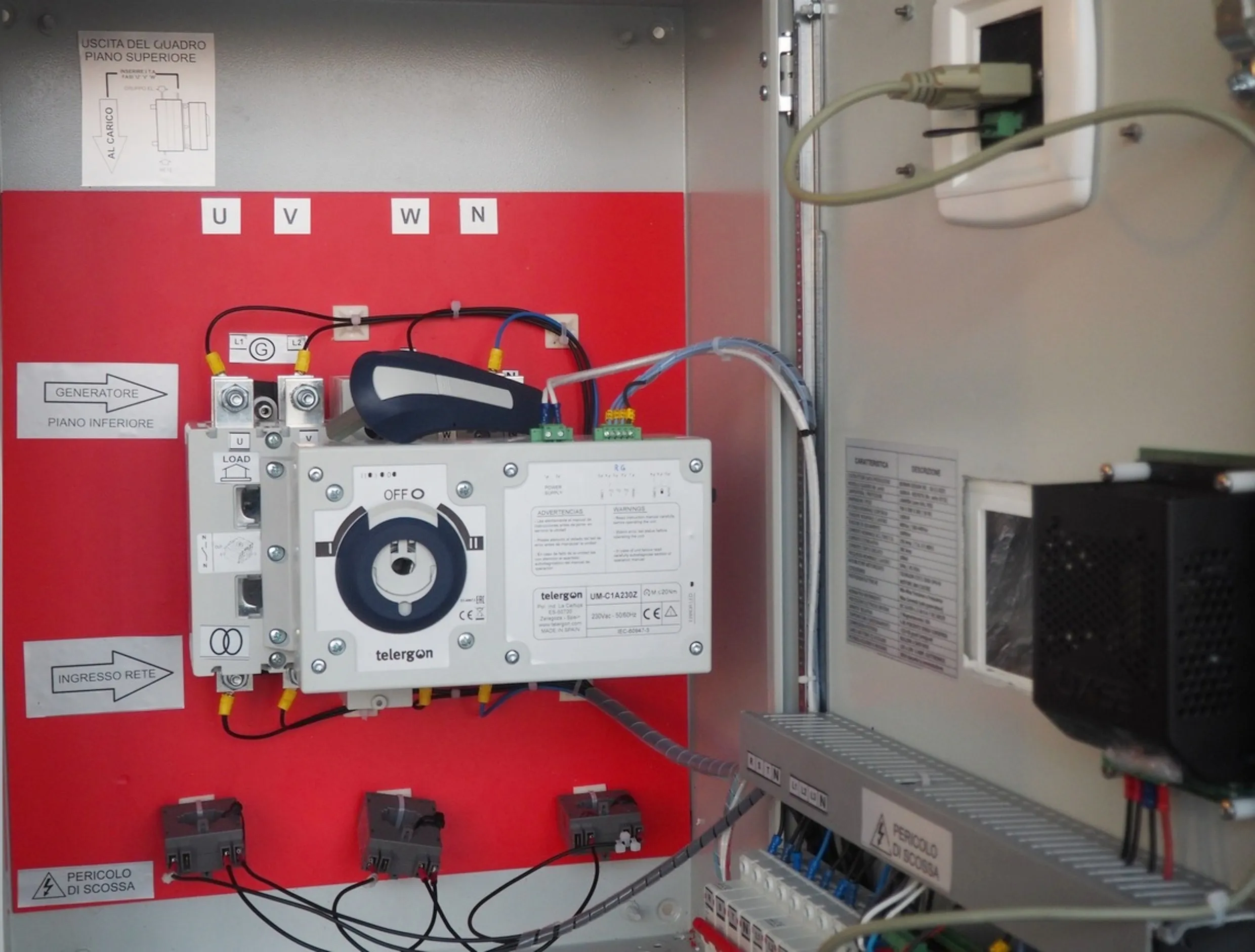
This ATS panel features a motorised-switch changeover technical solution.
| Description | Notes |
| Product origin /Manufacturer | EU/Bernini Design Srl |
| Model-ATS | 125A / BeK3 |
| Structure / Protection | Metal cabinet / 1,5mm / IP62 |
| External Dimensions | 700 X 500 X 260 / 25KG |
| Rated Nominal Power @ Ambient °C | 80 kVA @ 35°C |
| Continuous Power @ Ambient °C | 60 kVA @ 35°C |
| Rated Voltage (3-Ph+N) | 400 Vac / 360-440 Vac |
| Insulation Voltage | 1000 Vac |
| Rated Current AC1 @ 400Vac | 125 Amp |
| Continuous Current / Short Circuit | 0-100 Amp @ 400 V /50 kA |
| Frequency Range | 45 Hz - 55 Hz |
| Electrical Protections | Min-Max V-Hz, Max Amp |
| Changeover | 3-Ph+N Telergon 125A |
| Norms or Standards | IEC 61439-1-2-34-5-6-7 IEC 60529 |
| Internal Protections | 2 x Circuit Breakers 10 A 4-pole |
| Humidity Class | 5-85 % No condensation |
| Operating Temperatures | -5/+35 °C Nominal (50°C max.) |
| Temperature-Dependent Power Reduction | Reduce power 5% for each degree °C above 35 °C |
| Connections | Fastening using M8 hex bolts |
| Battery Charger | 12 V / 2 A |
| Standby Power Supply | 10 VA |
125 A / 25 kVA ATS Panel Installation Requirements
1) The panel must be installed only by qualified personnel.
2) Electrical protection devices must be installed to limit the power and current flowing through the panel, from the mains or generator, to a maximum of 150 amps at 400 volts.
3) Neutral and ground connections for the panel, mains and generator are mandatory.
4) The negative battery terminal must be grounded on the engine side. Do not ground the negative battery inside the panel.
5) Do not open the door when mains or generator voltage is present. The panel's interior contains components that present a risk of direct contact (IP00).
6) Consider placing advice about the presence of a standby generator on critical points.
Bernini Design Srl Italy