
ATS for Solar System Price: 399 €
Stop exposing your appliances to the risks of uncontrolled switching transitions.
Unlike a refrigerator’s natural cooling cycle, the switching process in common market-available ATS units often ignores back EMF. This oversight puts unnecessary stress on your equipment, significantly reducing the lifespan of your appliances over the long term.
Click to view full size
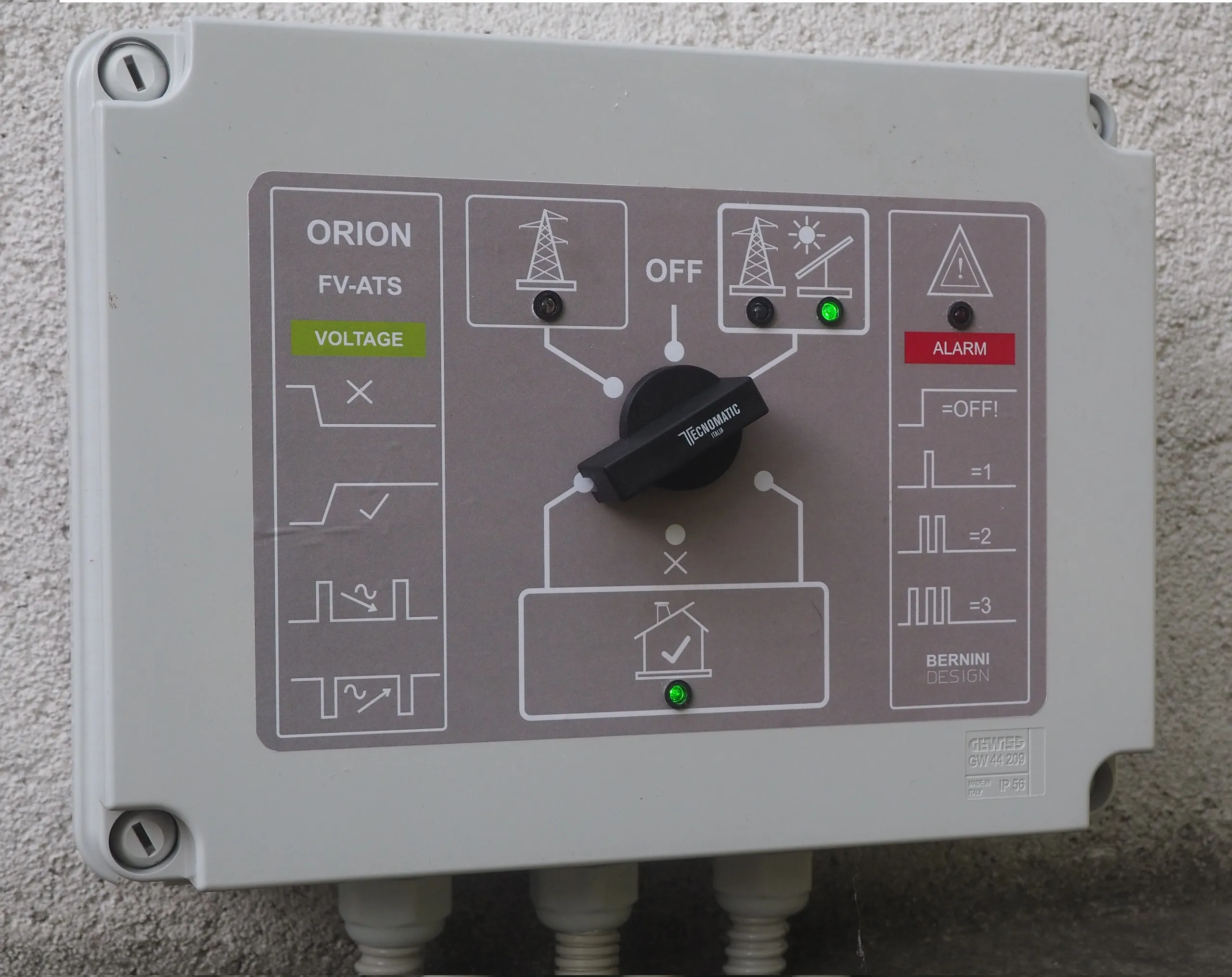
This ATS panel is suitable for a 5 Kw photovoltaic system. It is housed in a certified wall-mounted plastic enclosure and has a rated switching current of 32 :
Purchase the "ORION" ATS panel: 399 €
Free Shipping to EU.
+39 335 70 77 148
Order to: bernini@bernini-design.com
The ORION ATS panel offer extraordinary advantages over standard commercial ATSs
1) - Automatic Function: in the "AUTO" position, the panel connects the inverter to the house. When the inverter is out of service, the panel connects to the grid.
2) - Manual Function: it overrides all automatic operations and connects the house directly to the grid.
3) - Network Control: automatically connects to the network only if within the limits prescribed by regulations.
4) - Inverter control: the panel allows connection to the inverter only if it is within the limits specified by the regulations.
5) - Visual Indicators: the panel features intuitive light indicators for voltages and alarms.
6) - Protections: the ATS panel cuts off the power supply to the house if electrical parameters fall outside normal limits.
7) - Lightning and surges: the ATS panel is equipped with 10 pieces in parallel of S20K275 surge arresters capable of absorbing 20 kA (8/20 microseconds).
8) - Timed switching: unlike standard ATS units, the panel incorporates a safety pause that prevents damage to refrigerators.
9) - Auxiliary inputs: inputs for remote control signals, such as inhibit signals or special commands.
10) - Auxiliary outputs: control relays for external signals.
11) - Internal battery: lithium-based, rechargeable via mains or inverter; stores alarms in the event of a total power failure.
12) - Connections: 2 wires to the grid, 2 wires to the inverter, and 2 wires to the house. All via 3 easily detachable connectors.
13) - Switching technology: four-pole contactors with electrical and mechanical interlocking and manual bypass.
14) - Simple installation: GEWISS GW 44 209 wall-mounted enclosure with 4 mounting holes and 3 threaded PG21 cable entries.
Photovoltaic ATS: a comprehensive technical guide.
The problem: Battery depletion, inverter failure, or grid instability should not result in a blackout.
The solution: We provide custom-engineered ATS panels, not merely standalone switches. To ensure compliance and safety, a transfer panel must function as an integrated system. Our panels deliver the control logic, timed switching, and monitoring capabilities essential for modern photovoltaic installations, power plants, and industrial backup systems.
The advantage: Buy directly from the manufacturer, Bernini Design, and benefit from full support and service. A generic "PV ATS" unit found online could lead to unpleasant surprises.
Key specifications:
• Control logic: Industrial-grade programmable micro-architecture.
• Capacity: 32 A single-phase and three-phase versions available.
• Connectivity: Optional GSM remote control for status alerts and remote switching.
ORION ATS OVERVIEW
| TIPOLOGY | DESCRIPTION |
| Dimensions / Ingress Protection | 320mmx250mmx140mm / IP42 |
| Holes footprint | 250mm (base) 170mm (high) 4-hole |
| Weight | 3Kg |
| Relay Outputs | Positive Voltage (V batt) MAX 1A |
| Digital Inputs | Dry contacts, no voltage is allowed. |
| Load Maximum Peak Current (30 minutes) | 32A - 230V |
| Load Maximum Continuous Current | 25A - 230V |
| Recommended external circuit breaker protection rating | 25A - 230V |
| Internal ATS protection | 32A 10x38 Fuse |
| Surge Current | 20 kA
(8/20 microsecs.) |
| 12V Battery Charger | 12.8V 0,5A |
| Mains / Inverter Nominal voltage | 230V (210V-250V) |
| Surge Protections | 10 X S20K275 (TDK) |
| Frequency Range | 45Hz - 56Hz |
| Utility Power Short-Cuts detections | 500ms |
| Utility Power Transient Filter | T3 5…45 sec, 1..3 mins |
| Mains Failure - Restore time | T2 5…45 sec, 1..3 mins |
| Transfers Delay | T1 5…45 sec, 1…3 mins |
| Auto Change-over technology | 2x4-pole contactors
mechanical interlock (40 A /AC1) |
| Manual Change-over technology | 32 A switch 1-0-2 |
| Max cable size | 10 mmq |
| Norms compliance | EN61349X, 214/35/UE,
CEI121-5, 2014/30/UE |
| Environmental Conditions | -10/+40 °C / 85% |
| Certification /Warranty | CE/3-year |
What type of switch should a photovoltaic ATS panel use?
A search online reveals descriptions that are—to put it mildly—"sketchy" and potentially misleading. It is well established that the acronym ATS stands for "Automatic Transfer Switch," intuitively conveying the concept of an automatic switching device.
The idea that an ATS should transfer the load between two sources within a few milliseconds—without active synchronization—is sheer technical madness. Furthermore, anyone who uses the term "ATS" in this context lacks basic knowledge of electrical engineering. ATS units are motorized switches designed for industrial applications exceeding 125 amperes; they bear no relation to the standard contactor-based panels for single-phase systems (such as AMF units) found on the market.
The Bernini Design photovoltaic transfer panel features a programmable transition dead time. Describe your application to us, and we will provide the appropriate recommendation.
+39 335 70 77 148
This interval is crucial for dampening electrical transients generated by inductive and capacitive loads, thereby preventing dangerous voltage spikes or back-feed currents.
This safety measure can be ensured in two ways:
1) - A pair of mechanically interlocked contactors: typical of AMF (Automatic Mains Failure) panels.
2) - A motorized circuit breaker: typical of ATS (Automatic Transfer Switch) panels.
In both cases, the key lies not only in the mechanical components but also in the control electronics; advanced management software is essential to intelligently monitor and handle the dozens of possible combinations during the switching phase between power sources.
How does the photovoltaic transfer switch work?
Although commonly referred to simply as a "transfer switch," in actual system installations, this device is integrated into a specially designed panel: the "ATS" panel.
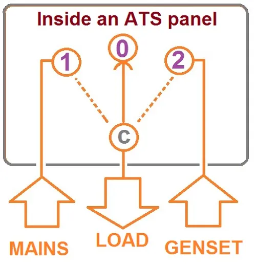
Certified according to current standards, the ATS panel contains a transfer switch ("C") that connects to node [1] to supply power to the home from the grid, to node [2] to supply power from the solar/photovoltaic system, and to the neutral position [0] to cut off the power supply to the home.
There are several ways to activate the photovoltaic transfer switch:
AUTOMATIC MODE
Automatic mode involves switching to the grid when:
1- The AC voltage or frequency is within programmed limits.
2- The storage battery voltage drops below a programmed threshold.
3- The inverter is overloaded or has shut down (locked out).
Click for full size image
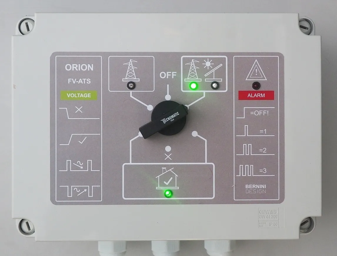
Automatic mode involves switching to photovoltaic power when:
1- The grid may be present or absent.
2- The storage battery has energy reserves.
3- The inverter supplies adequate voltage and frequency.
Click for full size image
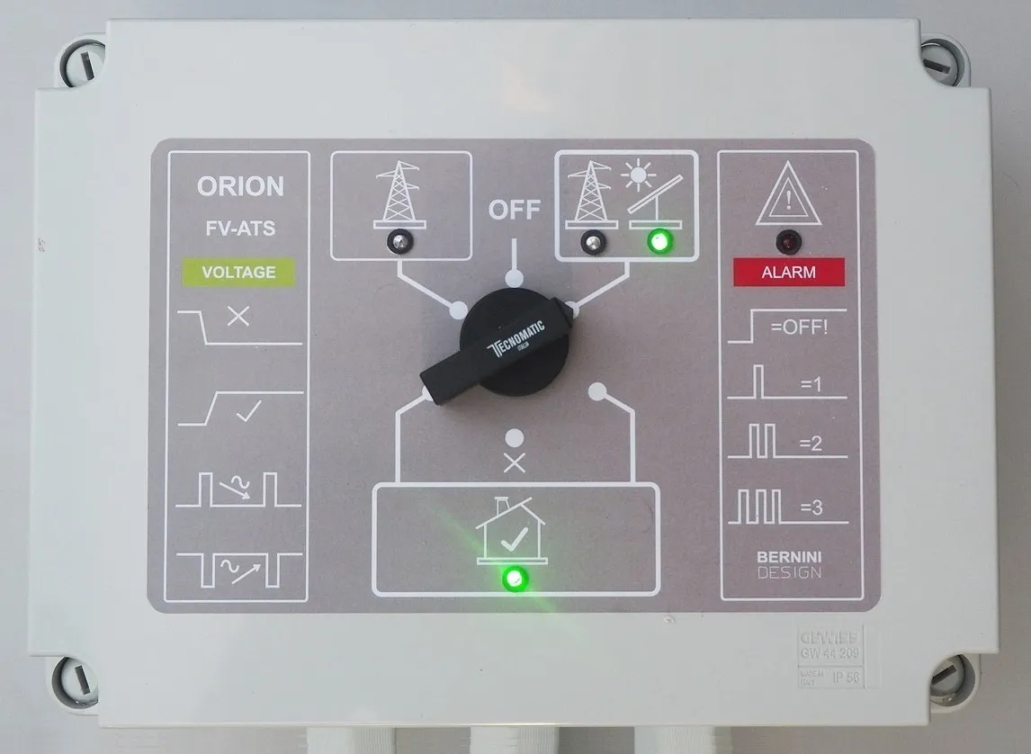
THE OFF MODE
The panel does not supply power to the house.
It is used to temporarily disconnect the electrical system when performing tests without interfering with the loads, which remain unpowered.
Click for full size image
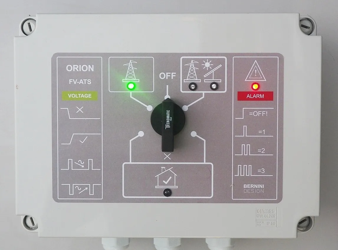
The OFF mode is indicated by the red alarm light remaining constantly on.
The unique feature of the Bernini Design ATS panel
THE BYPASS MODE
Using a purely electromechanical system that overrides all electronic logic, the Bernini Design photovoltaic panel draws power directly from the grid.
Click for full size image
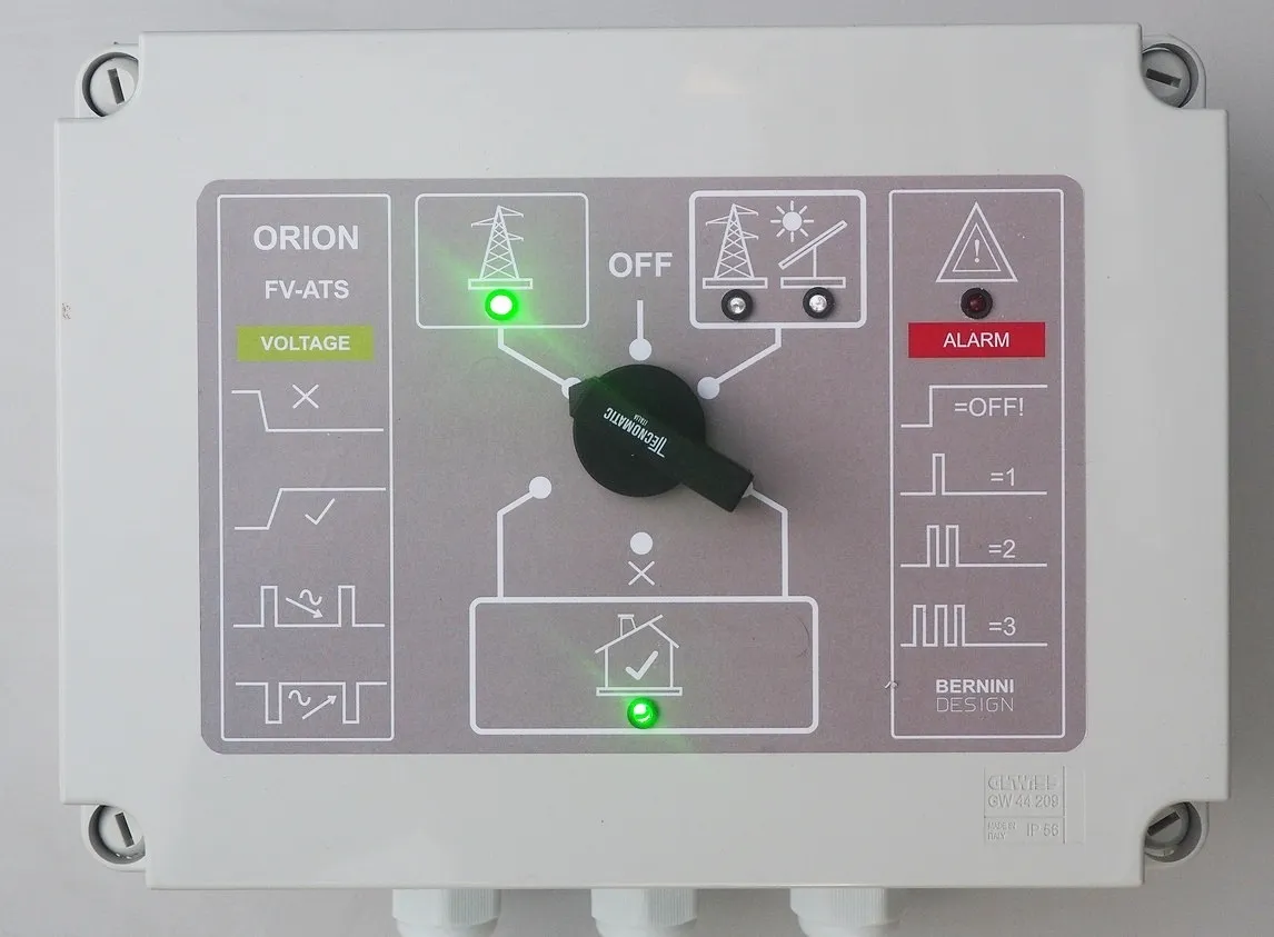
To be used when the photovoltaic system is not intended to be used for extended periods: the house is connected directly to the electrical grid. This function is also extremely useful in cases where catastrophic events—such as a powerful lightning strike—disable vital components of the control panel.
Basic photovoltaic transfer switch diagram
The diagram for the basic photovoltaic transfer switch is simple. Normally, the primary input is connected to the inverter. When the inverter can no longer operate—due to a lack of sunlight or depleted storage batteries—the transfer switch automatically connects the home to the electrical grid.
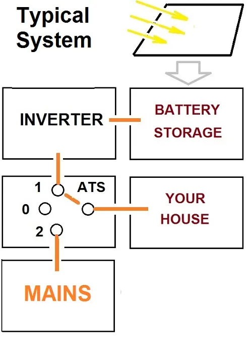
When operating conditions are suitable for the inverter, the transfer switch cuts off the grid supply. After a programmed delay designed to protect appliances, power is restored from the photovoltaic system.
Photovoltaic ATS diagram with a power generator
The photovoltaic ATS setup can also be used in complex applications where a generator compensates for the loss of grid power and a lack of solar energy. In this scenario, the generator can also be used to recharge the batteries, resulting in an excellent blackout protection system.
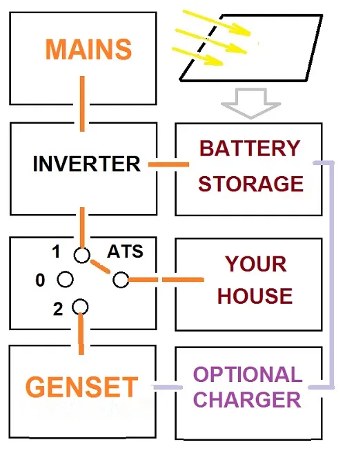 Under normal conditions, the storage system supplies power to the home, and excess energy is fed into the grid. When solar energy is depleted and a grid outage occurs simultaneously, the ATS triggers the generator to start. In addition to powering the home, the generator can optionally recharge the storage batteries.
Once the batteries are sufficiently charged, the generator stops automatically, and the system resumes drawing power from the storage unit.
If the grid outage persists and the batteries run low, the generator automatically restarts for another cycle. Naturally, the control unit integrated into the photovoltaic ATS features programmable settings to ensure optimal operation under all conditions.
Bernini Design Srl
Zona Industriale
46035 Ostiglia ITALY
bernini@bernini-design.com